
THRUST POSITION MONITOR SYSTEM (AXIAL) 7200
Displacement axial measurements
The working principle, the rotation of the rotor shaft, will cause movement of the shaft either positive or negative direction from the neutral / middle. The motion was detected by probe type and eddy currenr proximitor generating output electrical signal which is proportional to the distance between the probe shaft. Or observe the surface of the rotor.
Monitor changer proximitor to generate any output readings recorder position thrus and dc output signal proportional to the position of thrust. With the movement towards positive or negative shaft Which one will mengobah Thrus to individual dc signal level. DC level is then received by Indicator (Front panel meters), Recorder Driver Circuit. Alarm circuit can be adjusted by adjusting the set point, alarm indicator lights and signal relay alerts to be received. To keep from happening malfuntion or malfunctions then to make sure whether there is danger or not before the shutdown, then used AND logic, where if there is danger of a second transducer signal there will be a shutdown, if it happens one channel failure will not hear the alarm false.
12:17 captions, Proximitor merobah -24 Volt -18 Volt DC or DC to RF signal that is sent to the probe through a 95 ohm extension cable that causes alternating magnetic field. If there is no conductive material is cut, the magnetic field, there is no loss of power in the RF signal. With no power is lost in the RF signal, the output signal will approach proximitor -22 Volt DC (-24 Volt DC power supply).

Figure 12:17 Wiring diagram Dual Thrust Monitor
As the picture below is the theory of the Axial displacement measurement.

12:18 Picture Diagram Probe Thrust with Proximitor
Caption 12:18, When a conductive material (rotor shaft) approaching probe, eddy currents will be generated as the magnetic field is intersected by a conductive material (rotor shaft), which will result in loss of RF signal power or voltage will be reduced as well (directly proportional). When the surface of conductive material (rotor shaft) perilously close to the probe, the more power is absorbed through the eddy currents on the surface of the conductor material. When the probe is very close to the surface of conductive material (rotor shaft), then the maximum power is lost from the RF signal will be shown as the minimum output signal of proximitor. Proximitor will measure the amount of RF signal and is shown as a negative DC output signal, selanjudnya through an amplifier circuit. The monitor will show the amount of Axial Displacement happens as read on the meter.

12:18 Picture Position Probe against Thrust coller
Before we do the settings for the Axial Displacement, it first has to consider the following steps:
1. Determine the gap / clearance between the thrust collar and thrust bearing. for example: 0.32 mm.
2. Scale factor of proximitor must be known.
For example: have a scale factor proximitor 200mv/mils.
If the requirements are met prior to setting, then:
a. Move the rotor shaft to travel the maximum position on the dial reads micro meter by 0.32 mm, according to the calculations for the 0.32 mm gap = volts DC.
Given: proximitor scale factor 200 mV / mils.
1 = 25.4 mils (microns)
1 = 0.001 mm
1 mils = 25.4 x = 25.4 mm
1 mils = 200 mv
X 25.4 mm = 200 mV.

= 7.87 volts DC.
So: 0.32 mm = 0.32 x 7.87 Vdc = 2.5 Volts DC.
b. It is known from the calibration curve and proximitor probe.
eg: Voltage gap setting = 10 volts DC.
So the position of the shaft can be pushed to the maximum positive or negative travel, or when the voltage = 10 V
c. next when the rotor shaft is driven in the direction of travel set maximum positive Axial probe in such a way that a digital volt meter attached to the output terminals and the common proximitor reads 12.5 volts DC.
d. When the rotor shaft is driven in the direction of maximum negative trevel Axial probe set such that the digital volt meter attached to the output terminals and the common proximitor read 7.5 volts DC.
e. Selanjudnya observe on the monitor when the rotor shaft is driven trevel maximum positive or negative, the reading will symetris +0.16 mm and -0.16 mm to zero.
Caption 12:19, As with Radial Dual Vibration Monitor, so here also serves to change the monitor output signal to position proximitor thrust / axial monitor.
* If under normal conditions, the thrust position indicated:
- The meter 1.
- Indication lights OK "on" 2.
- Indication lights defeat, alart and danger "off" 3, 4 and 5.
* If the danger set AB switch is placed to the normal position, it will read normal danger point.
* If the danger set AB switch is placed to the normal position, it will read normal danger point.
* If alart set AB switch is placed to the normal position / counter, it will read normal alert set point / counter.
* To determine the output signal can be measured through proximitor proximitor A / B connector on the monitor.
* Defeat toggle switch is used to by-pass him one channel A / B when something is broken.

Figure 12:19 Thrust Monitor
TABLE 1. Fron INDICATOR PANEL, SWITCH, AND CONNECTOR INDEX no INDICATOR / SWITCH/ CONNECTOR FUNGTION
1 Meter (Zero-Center) Dual Display meter assembly to the thrust position and alert and danger set point for normal and counter directions upon switch selector. Standard meter contains mechanical movement, LED meter indicates measured value by illuminating an LED at the appropriate point on the meter scale.
2 A OK / B and OK (green) Indicator. Illuminated for each channel to indicate feild wiring is intact and operating gap voltage probes are within normal limits.
3 Defeat (Red) Indicator Indicates the channel with OK indicator has been extinguished Defeated (made inoperative).
4 ALERT (Red) indicator Indicates a specific preset alarm level has been thrust excaeded in either the normal or counter direction by either or both channels A and B. Normally set to indicate first warning.
DANGER 5 (Red) indicator
Indicates a specific preset alarm level has been thrust excaeded in either the normal or counter direction by either or both channels A and B. Normally set to indicate most severe warning.
6 7 DANGER SET AB / AB SET ALERT Toggle Switches
NORMAL position
COUNTER position
Used to display the alarm set point thrust in the normal direction for both channels simultaniusly. Is used with normal danger (ND) / normal alert (NA) set potentionmeter normal when adjusting alarm set point.
Same as NORMAL position except for counter direction. Is used with counter danger (CD) / counter alert (CA) SET potentiometer counter when adjusting alarm set point.
8 Prox VERT / Horiz connection. External connection to observe Individual proximitor output signal.
2. Calibrated of DVXY Monitor
A. Tools required for calibration.
1. HP3465A / B Digital Multimeter (DM) 4 ½ digit Digital Multimeter or Fluke 8000 3 ½ digits.
2. TK-3 Bently Nevada Test kalibration (range 0-1000 0-25 mils or mm)
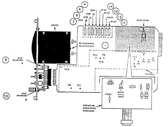
12:20 Picture Card for Thrust monitor
B. Thrust Axial Position Calibration Procedure
1. Set the meter mechnical zero, the condition of power OFF, set the set mechanical zero, is behind the meter indication posisnya see picture 12:20
2. Generate Calibration Signal, refer to paragraph 12.1 Gap calibration voltages representing the mechanical machine zero and full scale monitor (normal direction).
See Table-1, the required voltage on the meter range and transducer type. Calibration is one of them using a micrometer spindle of the TK-3 or variable dc power supply to generate a calibration voltage (voltage calibrator).
3. Adjust the zero (channel A), connected to signal calibration for point 7 (connection on the monitor). release from the recorder before calibration performed. Adjust the input voltage to zero. Adjust zero with a potentiometer, (4) hinga required voltage or current measured between 11 and common TP (meter scale reads zero)
4. Adjust the span and then the meter, Adjust the input voltage represents full-scale. Adjust the span potentiometer A, (9) after the required voltage level is reached or the current is measured between TP 11 and common (meter does not refer to full scale). Adjust the meter calibration potentiometer, (8), for full scale meter dfleksi.

12:20 Block diagram Figure thrus monitor
Caption:
Output proximitor forwarded to;
1. Buffer amplifier (2) proximiter output.
2. Differential amplifier (8) with output amplifier to the appointment of axial movement in normal meter / counter.
3. Output voltage external recorder (9).
4. Alart alarm circuit (11) and danger (12) which serves to compare the output amplifier (8) and (10) to the price of the alarm set point.
5. When the alert / danger set point is exceeded, then the alert / danger indicator lights and activate the relay danger that can be connected to the system trip of turbine / compressor
Figure 12:21 System Overview for system alarm and danger
Axial thrust posistion 12:22 Picture Calibration
Figure 12. 23 Spec. Thrust probe, proximitor and monitor
Tidak ada komentar:
Posting Komentar